Labb 25: HSRP 1 | Labb 27: HSRP 3
Spanning Tree Protocol erbjuder redundans fritt från loopar mellan switchar inom ett LAN. Det ger dock inte redundanta default gateway för slutenheter inom nätverket om en gateway-router fallerar. First Hop Redundancy Protocols (FHRP) erbjuder redundanta gateway utan ytterligare konfiguration från användarens sida. Genom att använda ett FHRP kan två eller flera routrar dela samma virtuella IP-adress och MAC-adress och agera som en enda virtuell router. Slutenheter på nätverket är konfigurerade med en delad IP-adress som deras default gateway.
I denna laboration implementeras Hot Standby Router Protocol (HSRP) i ett redundant nätverkstopologin med syftet att förstå bättre för hur FHRP och HSRP fungerar. Du kommer att konfigurera Hot Standby Router Protocol (HSRP) för att tillhandahålla redundanta default gateway-enheter till enheter på ett LAN. Efter konfigurationen av HSRP kommer du att testa konfigurationen för att verifiera att nätverksenheterna kan använda den redundanta default gateway om den nuvarande blir otillgänglig.
Nätverkstopologi
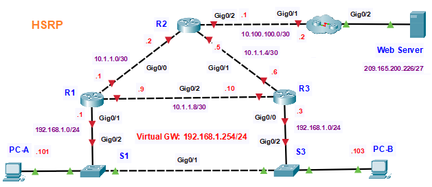
Alla routrar i topologin är av modellen 2911. I molnet finns en router och en switch (2960), till vilken ansluts webbservern. Routrarna R1 och R3 fungerar som default gateway för datorerna på LAN 1 respektive LAN 2. När du konfigurerar HSRP skapas en virtuell gateway som används som default gateway i båda LAN. Om en av gateway-routrarna blir otillgänglig, kommer den andra att överta rollen som default gateway. Eftersom nätverksenheterna är inställda att använda IP-adressen för den virtuella gateway kommer de att snabbt återfå anslutningen till externa nätverk när HSRP aktiverar den kvarvarande routern.
Konfigurationer
Att behålla instruktionerna på engelska kan det vara användbart för personer som är vana vid teknisk engelska, vilket ofta är fallet inom nätverksteknik och IT. Specifika engelska termer och koncept inom nätverksteknik kan ibland förlora sin exakthet eller innebörd om de översätts felaktigt.
I denna laboration börjar vi med att konfigurera grundinställningarna för alla nätverksenheterna. Efter det kommer vi att genomföra följande steg:
- Verifiera anslutningen
- Konfigurera aktiva och standby-routrar för HSRP
- Observera HSRP-funktionen
- Router> enable
- Router# configure terminal
- Router(config)# hostname R1
- R1(config)# no ip domain-lookup
- R1(config)# int g0/0
- R1(config-if)# ip address 10.1.1.1 255.255.255.252
- R1(config-if)# no shut
- R1(config-if)# exit
- R1(config)# int g0/1
- R1(config-if)# ip address 192.168.1.1 255.255.255.0
- R1(config-if)# no shut
- R1(config-if)# exit
- R1(config)# int g0/2
- R1(config-if)# ip address 10.1.1.9 255.255.255.252
- R1(config-if)# no shut
- R1(config-if)# exit
- R1(config)# router ospf 10
- R1(config-router)# log-adjacency-changes
- R1(config-router)# network 10.1.1.0 0.0.0.3 area 0
- R1(config-router)# network 10.1.1.8 0.0.0.3 area 0
- R1(config-router)# network 192.168.1.0 0.0.0.255 area 0
- R1(config)# end
- R1#
- Router> enable
- Router# configure terminal
- Router(config)# hostname R2
- R2(config)# no ip domain-lookup
- R2(config)# int g0/0
- R2(config-if)# ip address 10.1.1.2 255.255.255.252
- R2(config-if)# no shut
- R2(config-if)# exit
- R2(config)# int g0/1
- R2(config-if)# ip address 10.1.1.5 255.255.255.252
- R2(config-if)# no shut
- R2(config-if)# exit
- R2(config)# int g0/2
- R2(config-if)# ip address 10.100.100.1 255.255.255.252
- R2(config-if)# no shut
- R2(config-if)# exit
- R2(config)# ip route 0.0.0.0 0.0.0.0 10.100.100.2
- R2(config)# router ospf 10
- R2(config-router)# log-adjacency-changes
- R2(config-router)# network 10.1.1.0 0.0.0.3 area 0
- R2(config-router)# network 10.1.1.4 0.0.0.3 area 0
- R2(config-router)# network 10.100.100.0 0.0.0.3 area 0
- R2(config-router)# default-information originate
- R2(config-router)# end
- R2#
- Router> enable
- Router# configure terminal
- Router(config)# hostname R3
- R3(config)# no ip domain-lookup
- R3(config)# int g0/0
- R3(config-if)# ip address 192.168.1.3 255.255.255.0
- R3(config-if)# no shut
- R3(config-if)# exit
- R3(config-if)# int g0/1
- R3(config-if)# ip address 10.1.1.6 255.255.255.252
- R3(config-if)# no shut
- R3(config-if)# exit
- R3(config)# int g0/2
- R3(config-if)# ip address 10.1.1.10 255.255.255.252
- R3(config-if)# no shut
- R3(config-if)# exit
- R3(config)# router ospf 10
- R3(config-router)# log-adjacency-changes
- R3(config-router)# network 10.1.1.4 0.0.0.3 area 0
- R3(config-router)# network 10.1.1.8 0.0.0.3 area 0
- R3(config-router)# network 192.168.1.0 0.0.0.255 area 0
- R3(config)# end
- R3#
Switch S1 konfiguration
- Switch> enable
- Switch# configure terminal
- Switch(config)# hostname S1
- S1(config)# no ip domain-lookup
- S1(config)# interface Vlan1
- S1(config-if)# ip address 192.168.1.11 255.255.255.0
- S1(config-if)# no shut
- S1(config-if)# exit
- S1(config)# ip default-gateway 192.168.1.1
- S1(config)# end
- S1#
Switch S2 konfiguration
- Switch> enable
- Switch# configure terminal
- Switch(config)# hostname S2
- S2(config)# no ip domain-lookup
- S2(config)# interface Vlan1
- S2(config-if)# ip address 192.168.1.13 255.255.255.0
- S2(config-if)# no shut
- S2(config-if)# exit
- S2(config)# ip default-gateway 192.168.1.3
- S2(config)# end
- S2#
- Router> enable
- Router# configure terminal
- Router(config)# hostname ISP
- ISP(config)# no ip domain-lookup
- ISP(config)# int g0/1
- ISP(config-if)# ip address 10.100.100.2 255.255.255.252
- ISP(config-if)# no shut
- ISP(config-if)# exit
- ISP(config)# int g0/2
- ISP(config-if)# ip address 209.165.200.225 255.255.255.2224
- ISP(config-if)# no shut
- ISP(config-if)# exit
- ISP(config-if)# ip route 0.0.0.0 0.0.0.0 10.100.100.1
- ISP(config-if)# end
- ISP#
Part 1: Verify Connectivity
Step 1: Trace the path to the Web Server from PC-A.
a. Go to the desktop of PC-A and open a command prompt.
b. Trace the path from PC-A to the webserver by executing the tracert 209.165.200.226 command.
C:\>tracert 209.165.200.226

Tracing route to 209.165.200.226 over a maximum of 30 hops:

  1   *         0 ms      0 ms      192.168.1.1
  2   0 ms      0 ms      0 ms      10.1.1.2
  3   *         0 ms      0 ms      10.100.100.2
  4   *         12 ms     10 ms     209.165.200.226
Question:
Which devices are on the path from PC-A to the Web Server? Use the addressing table to determine the device names.
R1 , R2, ISP
Step 2: Trace the path to the Web Server from PC-B.
Repeat the process in Step 1 from PC-B.
C:\>tracert 209.165.200.226

Tracing route to 209.165.200.226 over a maximum of 30 hops:

  1   0 ms      0 ms      0 ms      192.168.1.3
  2   0 ms      1 ms      1 ms      10.1.1.2
  3   12 ms     21 ms     18 ms     10.100.100.2
  4   12 ms     11 ms     12 ms     209.165.200.226

Trace complete.
Question:
Which devices are on the path from PC-B to the Web Server?
R3, R2, ISP
Step 3: Observe the network behavior when R3 becomes unavailable.
a. Select the delete tool from the Packet Tracer tool bar and delete the link between R3 and S3.
b. Open a command prompt on PC-B. Execute the tracert command with the Web Server as the
destination.
C:\>tracert 209.165.200.226

Tracing route to 209.165.200.226 over a maximum of 30 hops:

  1   *         *         *         Request timed out.
  2   *         *         *         Request timed out.
  3   *         *         *         Request timed out.
  4   *         *         *         Request timed out.
  5
c. Compare the current output with the output of the command from Step 2.
Question:
What are the results?
The tracer command cannot determine the path to the Web Server because the path has been broken.
d. Click the Connections icon in the lower left corner of the PT window. Locate and select the Copper
Straight-Through icon in the pallet of connection types.
e. Click on S3 and select port GigbitEthernet0/2. Click R3 and select port GigabitEthernet0/0.
f. After the link lights on the connection are both green, test the connection by pinging the Web Server. The
ping should be successful.
Pinging 209.165.200.226 with 32 bytes of data:

Reply from 209.165.200.226: bytes=32 time<1ms TTL=125
Reply from 209.165.200.226: bytes=32 time=12ms TTL=125
Reply from 209.165.200.226: bytes=32 time=11ms TTL=125
Reply from 209.165.200.226: bytes=32 time=12ms TTL=125

Ping statistics for 209.165.200.226:
    Packets: Sent = 4, Received = 4, Lost = 0 (0% loss),
Approximate round trip times in milli-seconds:
    Minimum = 0ms, Maximum = 12ms, Average = 8ms
Part 2: Configure HSRP Active and Standby Routers
Step 1: Configure HSRP on R1.
a. Configure HSRP on the G0/1 LAN interface of R1.
R1(config)# interface g0/1
b. Specify the HSRP protocol version number. The most recent version is version 2.
Note: Standby version 1 only supports IPv4 addressing.
R1(config-if)# standby version 2
c. Configure the IP address of the virtual default gateway.
This address must be configured on any hosts that require the services of the default gateway. It replaces the physical interface address of the router that has been previously configured on the hosts.
Multiple instances of HSRP can be configured on a router. You must specify the HSRP group number to identify the virtual interface between routers in a HSRP group. This number must be consistent between the routers in the group. The group number for this configuration is 1.
R1(config-if)# standby 1 ip 192.168.1.254
d. Designate the active router for the HSRP group.
It is the router that will be used as the gateway device unless it fails or the path to it becomes inactive or unusable. Specify the priority for the router interface. The default value is 100. A higher value will determine which router is the active router. If the priorities of the routers in the HSRP group are the same, then the router with the highest configured IP address will become the active router.
R1(config-if)# standby 1 priority 150
R1 will operate as the active router and traffic from the two LANs will use it as the default gateway.
e. If it is desirable that the active router resume that role when it becomes available again, configure it to preempt the service of the standby router. The active router will take over the gateway role when it becomes operable again.
R1(config-if)# standby 1 preempt
Question:
What will the HSRP priority of R3 be when it is added to HSRP group 1?
100, which is the default value.
Step 2: Configure HSRP on R3.
Configure R3 as the standby router.
a. Configure the R3 interface that is connected to LAN 2.
b. Repeat only steps 1b and 1c above.
R3(config)# interface g0/0
R3(config-if)# standby version 2
R3(config-if)# standby 1 ip 192.168.1.254
R3(config-if)# end
R3#
Step 3: Verify HSRP Configuration
a. Verify HSRP by issuing the show standby command on R1 and R3. Verify the values for HSRP role,
group, virtual IP address of the gateway, preemption, and priority. Note that HSRP also identifies the
active and standby router IP addresses for the group.
R1# show standby
GigabitEthernet0/1 - Group 1 (version 2)
State is Active
4 state changes, last state change 00:00:30
Virtual IP address is 192.168.1.254
Active virtual MAC address is 0000.0C9F.F001
Local virtual MAC address is 0000.0C9F.F001 (v2 default)
Hello time 3 sec, hold time 10 sec
Next hello sent in 1.696 secs
Preemption enabled
Active router is local
Standby router is 192.168.1.3
Priority 150 (configured 150)
Group name is "hsrp-Gi0/1-1" (default)
R3# show standby
GigabitEthernet0/0 - Group 1 (version 2)
State is Standby
4 state changes, last state change 00:02:29
Virtual IP address is 192.168.1.254
Active virtual MAC address is 0000.0C9F.F001
Local virtual MAC address is 0000.0C9F.F001 (v2 default)
Hello time 3 sec, hold time 10 sec
Next hello sent in 0.720 secs
Preemption disabled
Active router is 192.168.1.1
MAC address is d48c.b5ce.a0c1
Standby router is local
Priority 100 (default 100)
Group name is "hsrp-Gi0/0-1" (default)
Using the output shown above, answer the following questions:
Questions:
- Which router is the active router?
R1 - What is the MAC address for the virtual IP address?
0000.0C9F.F001 - What is the IP address and priority of the standby router?
The IP address is 192.168.1.3 and the priority is 100.
b. Use the show standby brief command on R1 and R3 to view an HSRP status summary. Sample output
is shown below.
R1# show standby brief
P indicates configured to preempt.
|
Interface Grp  Pri  P  State  Active  Standby       Virtual IP
Gi0/1     1    150  P  Active local   192.168.1.3   192.168.1.254

R3# show standby brief
P indicates configured to preempt.
|
Interface  Grp  Pri  P   State     Active        Standby    Virtual IP
Gi0/0      1    100      Standby   192.168.1.1   local      192.168.1.254
c. Change the default gateway address for PC-A, PC-C, S1, and S3.
Which address should you use?
The default gateway is now 192.168.1.254
S1(config)# ip default-gateway 192.168.1.254
S3(config)# ip default-gateway 192.168.1.254
Verify the new settings. Issue a ping from both PC-A and PC-C to the Web Server. Are the pings successful?
yes!
Part 3: Observe HSRP Operation
Step 1: Make the active router become unavailable.
Open a command prompt on PC-B and enter the command tracert 209.165.200.226.
S1(config)# ip default-gateway 192.168.1.254
Question:
Does the path differ from the path used before HSRP was configured?
Yes. The path now passes through R1 instead of R3
Step 2: Break the link to R1.
a. Select the delete tool from the Packet Tracer toolbar and delete the cable that connect s R1 to S1.
b. Immediately return to PC-B and execute the tracert 209.165.200.226 command again. Observe the output of the command until the command completes execution. You may need to repeat the trace to see the full path.
Question:
How was this trace different from the previous trace?
At first, the trace timed out. Eventually, the trace went through R3, and ISP. R3 was used as the first hop gateway in this trace instead of R1.
HSRP undergoes a process to determine which router should take over when the active router becomes unavailable. This process takes time. Once the process is complete, the R3 standby router becomes active and is used as the default gateway for hosts on LAN 1 and LAN 2.
Step 3: Restore the link to R1.
a. Re-connect R1 to S1 with a copper straight-through cable.
b. Execute a trace from PC-B to the Web Server. You may need to repeat the trace to see the full path.
Questions:
What path is used to reach the Web Server?
At first the trace fails. Eventually it begins using R1 as the gateway again.
If the preempt command was not configured for the HSRP group on R1, would the results have been the
same?
No, R1 would not become the gateway again. The path through R3 would continue to be used.